Introduction
Sketching is a fundamental skill in 3D modeling, particularly in Fusion 360, a popular computer-aided design (CAD) software. Many users new to Fusion 360 often struggle to create high-quality 3D models without a solid understanding of sketching principles. In this blog post, we’ll explore why sketching is the foundation of 3D modeling in Fusion 360 and provide practical tips to help you improve your skills.
The Importance of Sketching in 3D Modeling
Before diving into the specifics of Fusion 360, let’s discuss why sketching is essential in 3D modeling. A 3D model is essentially a collection of 2D sketches that are extruded or lofted to create the final shape. Think of it like building with blocks: you start with individual blocks (2D sketches) and then assemble them to create a 3D structure.
In Fusion 360, sketches are the building blocks of your 3D model. You create a sketch by drawing 2D shapes and curves, which are then used to create the 3D model. This process allows you to create complex shapes with precision and accuracy. Without a solid understanding of sketching, it’s challenging to create high-quality 3D models.
Understanding Sketching Fundamentals in Fusion 360
To create successful sketches in Fusion 360, you need to understand the fundamentals of sketching. Here are some key concepts to grasp:
Understanding the Coordinate System
The coordinate system is the foundation of sketching in Fusion 360. Familiarize yourself with the X, Y, and Z axes, as well as the origin point (0, 0, 0). This will help you create accurate sketches and avoid common mistakes.
Creating Basic Shapes
Fusion 360 provides a variety of basic shapes, including lines, arcs, circles, and rectangles. Practice creating these shapes to develop your sketching skills. You can also create custom shapes by combining basic shapes or using the sketching tools.
Working with Dimensions and Constraints
Dimensions and constraints are essential in maintaining the accuracy of your sketches. Learn to use dimensions to define the size of your sketches and constraints to define the relationships between them.
Practical Examples of Sketching in Fusion 360
Let’s apply the concepts we’ve discussed so far to create a simple 3D model in Fusion 360. We’ll create a basic box with a hole in it.
Creating the Box
To create the box, we’ll start by creating a sketch of the box’s shape. We’ll use the rectangle tool to create the top and bottom faces, and then use the extrude tool to create the sides.
Creating the Hole
To create the hole, we’ll create a new sketch and use the circle tool to draw a circle. We’ll then use the extrude tool to create the hole.
Advanced Sketching Techniques in Fusion 360
Once you’ve mastered the basics of sketching, you can move on to more advanced techniques. Here are a few examples:
Using Curves and Splines
Curves and splines are essential in creating smooth, continuous shapes. Learn to use the curve tool to create smooth curves and the spline tool to create complex shapes.
Applying Symmetry and Mirroring
Symmetry and mirroring are useful techniques for creating symmetrical shapes and reducing the complexity of your sketches. Learn to use the symmetry tool to create symmetrical shapes and the mirror tool to create mirrored shapes.
Conclusion
Sketching is the foundation of 3D modeling in Fusion 360. By understanding the fundamentals of sketching, including the coordinate system, basic shapes, dimensions, and constraints, you’ll be well on your way to creating high-quality 3D models. Practice creating simple sketches and gradually move on to more complex projects. Remember to experiment and explore the advanced sketching techniques in Fusion 360 to take your skills to the next level.
FAQ
Q: What is the difference between a 2D sketch and a 3D model?
A: A 2D sketch is a 2D drawing that represents a 2D shape or object. A 3D model is a 3D representation of a 3D object or shape, created by extruding or lofting 2D sketches.
Q: How do I create a new sketch in Fusion 360?
A: To create a new sketch in Fusion 360, go to the “Sketch” tab in the top menu and click on “New Sketch.” You can also create a new sketch by selecting “Sketch” from the “Create” menu.
Q: What is the purpose of dimensions in sketching?
A: Dimensions in sketching are used to define the size and shape of your sketches. They help maintain the accuracy of your sketches and ensure that your 3D model is created correctly.
Q: How do I use constraints in sketching?
A: Constraints in sketching are used to define the relationships between different elements in your sketch. They help maintain the accuracy of your sketches and ensure that your 3D model is created correctly.
Q: Can I use Fusion 360 to create 2D drawings?
A: Yes, Fusion 360 can be used to create 2D drawings. However, Fusion 360 is primarily a 3D CAD software, and its 2D drawing capabilities are more limited compared to other CAD software.
Q: What is the difference between a sketch and a part in Fusion 360?
A: A sketch is a 2D drawing that represents a 2D shape or object. A part is a 3D object or shape created by extruding or lofting a sketch.
End of Blog

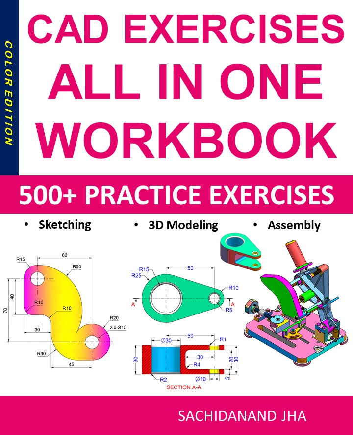
Autodesk Fusion 360 All-in-One Workbook
500+ Practice Exercises to Master Autodesk Fusion 360 through real-world practice!
This all-in-one workbook is your ultimate resource to develop hands-on CAD skills with Autodesk Fusion 360. Whether you’re a student, engineer, hobbyist, or professional, this guide is built to help you gain real design confidence through structured practice.
What’s Inside this Book:
- 200 2D Sketching Exercises – Build a strong foundation in dimension-driven 2D geometry and technical drawings
- 200 3D Modeling Exercises – Practice modeling real-world parts, from simple shapes to complex components.
- Multi-Part Assembly Projects – Understand how parts fit together and create full assemblies with detailed drawings
🎯 Why This Book?
- 500+ practice exercises following real design standards
- Designed for self-paced learning & independent practice
- Perfect for classrooms, technical interview preparation, and personal projects
- Covers 2D Sketching, 3D Modeling & Assembly Design in one workbook
- Trusted by 15,000+ CAD learners worldwide